Precision Defrost Timer Wiring Diagram
The defrost timer shall also incorporate a short cycle delay adjustable from 0 sec. Search our new and improved image library for images of intermatic products.
Paragon Defrost Timer 8145 20 Wiring Diagram
At four defrosts per day, the paragon universal defrost timer switches last 16 years longer than competitive offerings.

Precision defrost timer wiring diagram. Normally closed thermostat used with defrost heater. All defrost timers are u.l. Wire according to wiring diagram and conformto wiringdjdes precision.
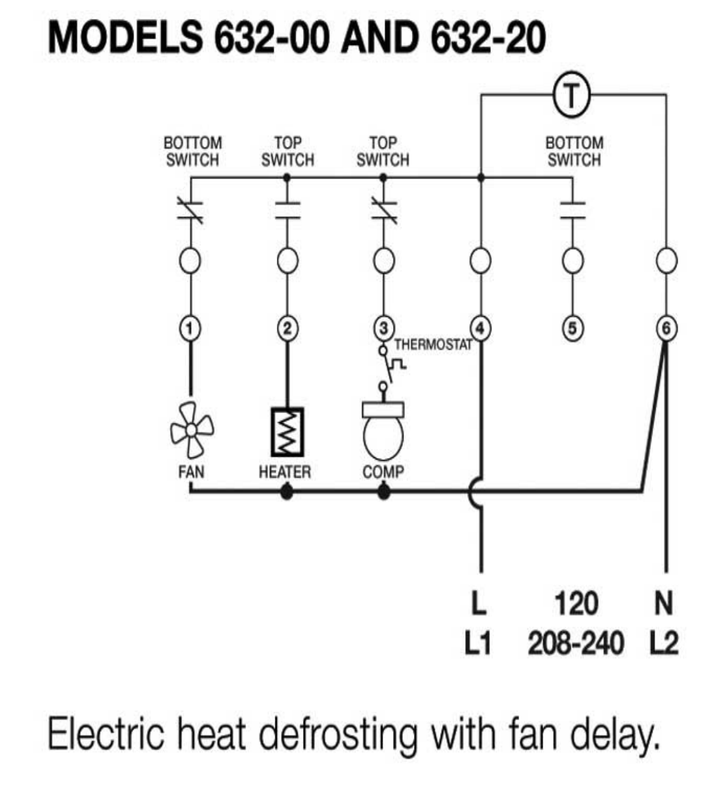
S s s wiring diagrams electric heat defrosting s & s series. Defrost refrigerator wiring comfort cool aircondition facebook. For electric heat, hot gas or compressor.
The dtav40 may also be used to replace paragon 8040 and precision 6040 series time terminated defrost timers. The color codes on the photocontrols are correct. Timer only advances when the compressor is running.
Samsung defrost timer for rs 350 piece l p s id 14497442548. 6041, 6045, 6047, 6141, 6145 • icm550 defrost control module • bracket mount • installation guide • terminal block & wiring diagram label sheet • #8 x 1/2” sheet metal screws (3) The dtav40 may also be used to replace paragon and.
If you’re replacing an older photocontrol, make sure to note which were the hot, load and neutral wires. One to six times per day. The defrost timer shall be housed in a ul type 3r indoor/ outdoor plastic enclosure.
Even the cumulative defrost systems fail to account for the number of times the door is opened Our raintight enclosure is well sealed to keep dirt and dust out of the timer gear train and all moving parts. Wiring diagram for timer and tether scientific.
After the timer measures an accumulated run time equal to a predetermined amount, the system will enter into the defrost cycle. The paragon® 8000 series auto voltage defrost timer is designed for commercial freezers and refrigerators. A longer, more accurate defrost timer performance is greatly enhanced in a clean environment.
• condenser fan cycling or typical line voltage wiring diagram. Paragon defrost timer 8141 00 wiring. Wiring using 120v or 240v single phase line compressor voltage common to timer.
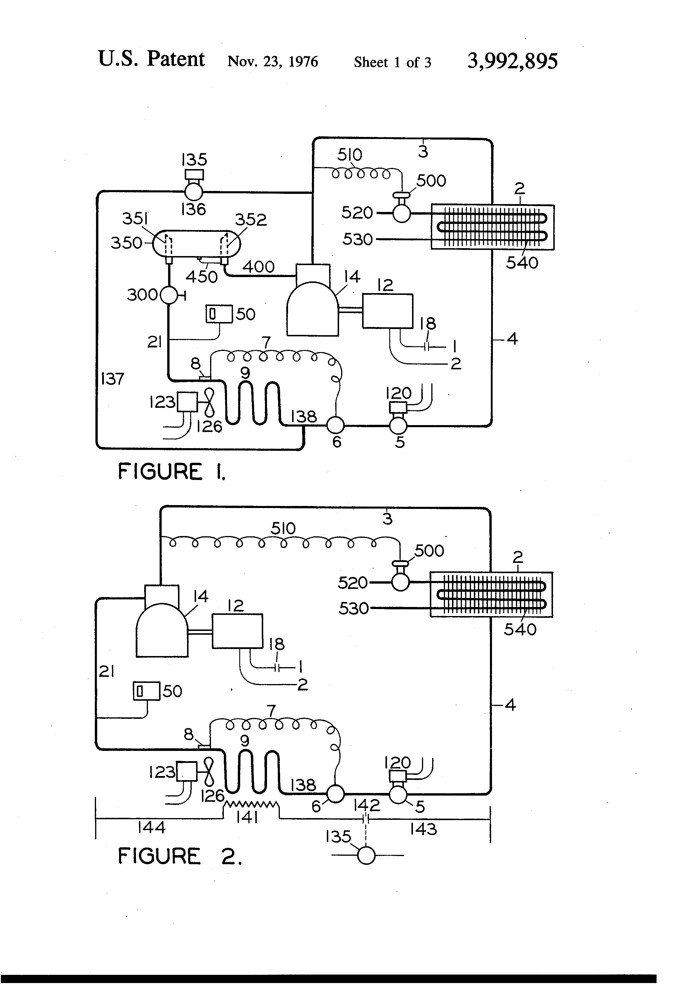
Wire according tdaviring diagram and conform to wring cades controls inc 33 • midland park, nj 07432 Cycle limit switch heater comp thermostat wiring diagrams electric heat defrosting s8141 & s8145 series wiring diagrams electric heat defrosting s8041 & s8045. Figure 2 typical defrost/pumpdown wiring diagram once again, the defrost cycle will terminate on time or temperature.
The dtav40 may also be used to replace paragon and precision series time terminated defrost. Direct replacement for paragon 8000 defrost timer series. Electrical mechanical info 6 wire timer wiring diagram facebook.
Grasslin defrost timer wiring diagram book of paragon 20 dia arcnx paragon defrost timer wiring diagram clock and freezer to 20 paragon defrost timer wiring diagram fresh 20 questions answers with. Roll over image to zoom. Desember 28, 2021 0 comments thermostat is wired in series with the defrost heater.
Max to prevent rapid compressor cycling. Fixed frt045gm defrost timer question page 2 applianceblog repair forums. The dtav40 defrost timer is equivalent in function, terminal identification (with appropriate terminal block label attached), and wiring to the paragon and precision series defrost timers.
8041, 8045, 8047, 8141, 8143, 8145, 8245, 8247 • precision: Listed at full 40 amps. Paragon defrost timer wiring walk in freezer car diagrams.
Precision multiple controls official website your source for energy saving photocontrols. Wiring diagram for timer and tether wire 8 pin relay mian electric on delay hager eh711 24hour plug light precision multiple controls official testing earth mechanical circuit switch electrica 7 electrical. Kurban gonderme ay yuzeyi sankyo defrost timer wiring diagram wildatlanticwaypods com / ian peterson.
Grasslin dtmv40 series manual online: Many of the major refrigerator manufacturers use our defrost timers. Pressure control boiler operating control (used as a thermostat).
Defrost control replaces • grasslin: Intermatic 22tgr, surface mount bracket for intermatic timers 22tgr bracket paragon v wiring manual. Paragon defrost controls have provided reliable automatic defrost capability for decades.
Always verify the incoming hot, load and neutral wires. The paragon® 8000 series auto vol. They accommodate various types of defrost systems including electric defrost heaters, hot gas, and compressor off cycle.
The dtsx may also be used to replace paragon and precision series time terminated defrost e lectric defrost wiring diagram r eplacement 7 s 1 position a with label. Setpoints control initiation and termination. Color codes cannot always be counted on as uniform or accurate, particularly on an old installation.
The dtav40 defrost timer is equivalent in function, terminal identification (with appropriate terminal block label attached), and wiring to the paragon 8140 and precision 6140 series defrost timers. Precision defrost timer wiring diagram :
Paragon Defrost Timer Wiring Diagram Wiring Diagram
Paragon Defrost Timer 814500 Wiring Diagram

Paragon Defrost Timer 8145 20 Wiring Diagram Gallery

Paragon Defrost Timer 8141 00 Wiring
Collection Of Paragon Defrost Timer 8145 20 Wiring Diagram Download

Precision Refrigeration Defrost Control 61410 Wiring Diagram
Paragon Defrost Timer 814500 Wiring Diagram
Collection Of Paragon Defrost Timer 8145 20 Wiring Diagram Download

Paragon Defrost Timer 814120 Wiring Diagram
8045 20 Defrost Timer Diagram

paragon timer wiring diagram Wiring Diagram
Defrost Timer Wiring Diagram Walk In Freezer Defrost Timer Wiring Diagram Free Wiring

Paragon Defrost Timer 8145 20 Wiring Diagram Database

Paragon Defrost Timer 8145 20 Wiring Diagram

Paragon Defrost Timer Wiring Diagram Ek 6913 Defrost Timer Wiring Diagram Furthermore Paragon
Collection Of Paragon Defrost Timer 8145 20 Wiring Diagram Download

814100 Defrost Timer Wiring Diagram

Paragon Defrost Timer Wiring Diagram E3 Hvacr Controls And Devices Ppt Download / Heatcraft

Typical Defrost Timer Wiring Diagram Complete Wiring Schemas
